Back to basics: AVR et al.
I was looking closely for a long time to Arduino, however it looked to me always as a way too narrow or too specialised solution. Until I stumbled upon this. And here I understood - I simply must have it.
Moreover, I already had PL2303 USBtoTTL232 converter playing dead in my waste box. I also found plenty of ATmega238P sold at fair price on ebay with bootloader pre-burned. So nothing could stop me. Couple of hours browsing over ebay, collecting required components, couple of days waiting for delivery - and voila here it is!
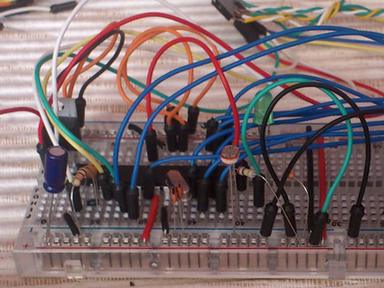
Here we have: At the right corner is stabilizer (although I'm using it rather as voltage reduction) at the centre is Atmega328P, below is 16MHz crystal and 2 caps, right of crystal I plugged photoresistor to check ADC, in the background at the top is a pin header I use to connect wires to PL2303 (which I re-soldered to get additional signals like DTR).
Speaking of DTR and PL2303. DTR is used by default in Arduino IDE for bootloaded MCUs to initiate self-programming sequence. Basically it just resets MCU at required time. You may do it manually when you know the timing - you can just practice a bit, no harm here as with wrong timing upload simply fails and Arduino boots normally.
PL2303 is quite cheap (and as I mentioned somewhere I already had it) although in my case (Nokia C42 cable) it had only three wires - GND, Tx and Rx. That's enough for manual reset sequence, but browsing here and there I found that most of the time PCB comes with full RS(CMOS)232 set of IOs - that is Gnd, Rx, Tx, DTR, CSR, RTS, CTS, DCD and RI. But only those required for particular application are soldered. After I cut rubber coating off USB stick it was revealed to be correct - all 10(!) were there, with addition of +5V. So after a bit of soldering I got full-blown TTL/CMOS 232 USB adapter.
One additional detail - reset should be pulsed at right time, however serial port open just drives DTR low till the port is in use. So if you just connect DTR to RESET pin - it will keep ATmega in reset state while trying to upload something. Easy solution is just to put some small capacitor between dtr and reset. Granted the RESET is pulled high (as it should) it gives us right pulse time while 100pF cap is charging between pull-up and DTR.
That's pretty it - just fire up Arduino IDE and push some sketch (I wouldn't stop here in serial port permissions details - there're plenty of docs regarding it over the net).
Link... Sat Nov 2 22:39:24 2013 Upd.: Sun Nov 3 16:02:58 2013